Debug Card
The first Stargazer Debug Card was intended to break out the SWD lines (Clock, Data In/Out, Ground, and Reset) for each card. It also provided a connector for the Keyboard to connect to the Arbitrator via UART.
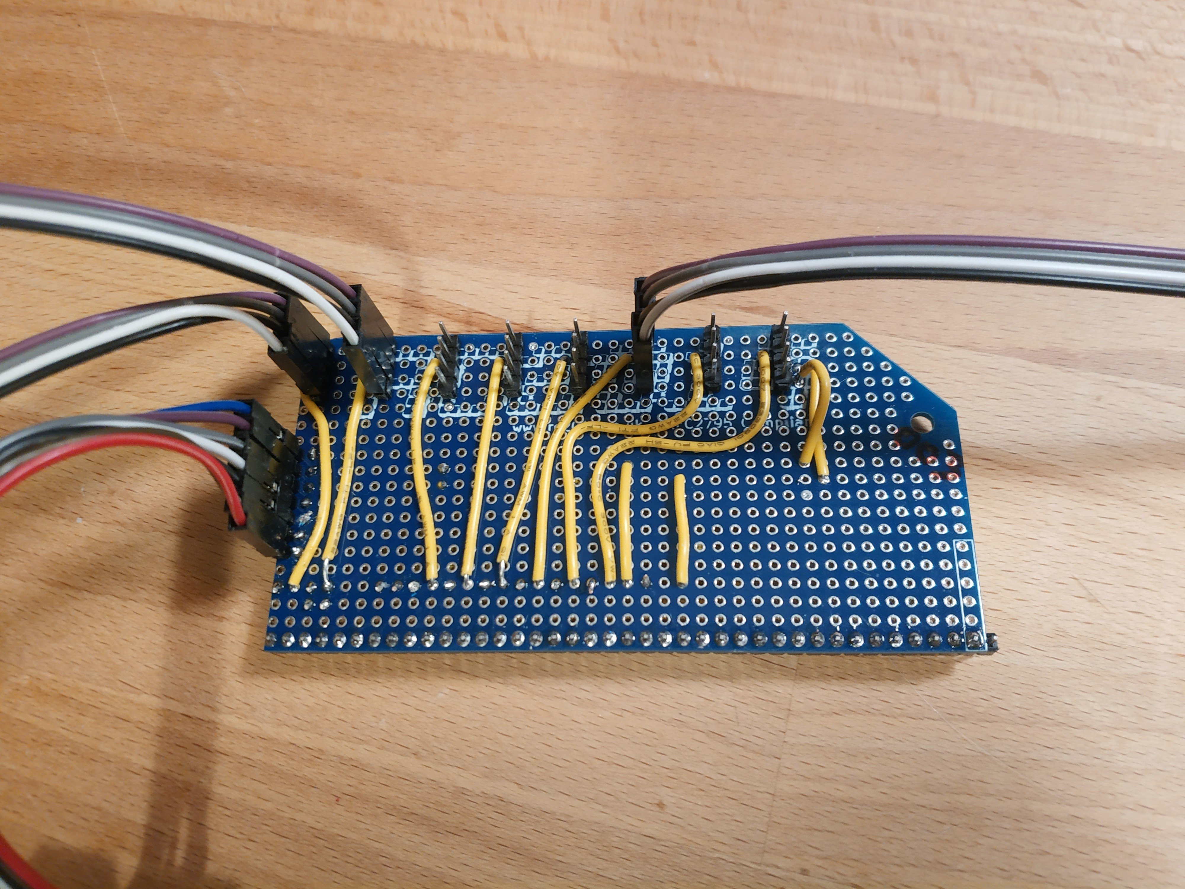
It was built on top of an RC2014 Prototype card.
Note that Pin 1 was actually ABOVE the card, as the Prototype card only had 39 pins.
For a list of signal lines, please see the Backplane Page.
Pinout
The following pinout was used for each of the debug headers. This is from Left to Right.
| Pin Number | Color in Photo | Signal |
|---|---|---|
| 1 | Purple | CARDn-SWDCLK |
| 2 | Grey | CARDn-SWDIO |
| 3 | Black | Ground (common) |
| 4 | White | Reset (common) |
The headers were connected in the following order, Top to Bottom:
- Card 1 SWD
- Card 2 SWD
- Card 3 SWD
- Card 4 SWD
- Card 5 SWD
- Card 6 SWD
- Card 7/Keyboard SWD (common)
- Arbitrator SWD
Below all SWD headers, is a Keyboard Header. This pinout matches the headers on the MakerDiary M60. These pins are numbered from Left to Right
| Pin Number | Color in Photo | Signal |
|---|---|---|
| 1 | Blue | Key-TXD/Arb-RXD |
| 2 | Purple | Key-RXD/Arb-TXD |
| 3 | Grey | SWDIO |
| 4 | White | SWCLK |
| 5 | Black | RESET |
| 6 | Brown | Ground (common) |
| 7 | Red | +3v3 |